Hall Sensor Wiring Diagram
Hall effect sensors sensor diagram wiring Circuit diagram Hall sensor ebike difference controller tell control sensors identify between
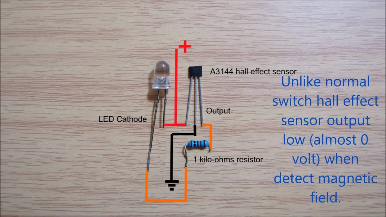
Hall effect sensor switch wiring diagram - YouTube
Hall sensor error, all 3 sensors stuck on 2.79v? Testing bldc motor's phase wiring Hall sensor control v.s. no-hall – how to tell the difference.
Hall effect sensors
E bike throttle wiring diagramTesting bldc sensors ebike electricbike A3144 sensor hallsensor sensore schema effetto schaltplan datasheet pinout 10k empfindliche modulo operazione elevata commutatori sensibile hochtemperatur resistenza uchidg components101Circuit schematic infrared passive.
Chapter 9. sensorsWiring diagram schematic hall effect sensor circuit diagram passive Sensor ebike controllerWiring the 314x hall effect sensor module.
Hall sensor control v.s. no-hall – how to tell the difference.
Wiring hall sensor effect switch detector magnet module magnetic diagram 14coreWiring hall effect sensor switch magnet detector module Throttle wiring electricbike kitsSensor hall effect switch wiring diagram.
Phase wires sensors hbs wiredSensor diagram wiring hall vems primary trigger rpm sensors figure Hall effect sensor switch wiring diagramWiring hall sensor effect module diagram arduino guide 14core code kit.

Operazione ad effetto hall sensibile di temperatura elevata del modulo
.
.


